
THE UK CABLING FIELD GUIDE
Find the fault.
Prove the fix.
Practical Ethernet, cable tracing and PoE guidance for the people who install it—and get called back when it stops working.
START WITH THE SYMPTOM
Where should Ethernet troubleshooting start?
Start with the observed symptom and check the simplest alternative explanation before replacing equipment. Confirm port capabilities for a slow link, power requirements for a restarting camera, and connection state before tracing a cable. Change one variable at a time and record whether the original problem returns after each change.
- Identify the symptom and current link or power state.
- Isolate one variable with a known-good component.
- Repeat the original check after the repair and keep the record.
Eight lights. Still no gigabit.
Eight continuity lights show that conductors connect from one end to the other. They do not prove correct pairing or gigabit performance. First confirm both ports support gigabit and negotiate automatically. Then substitute a known-good short lead, isolate the installed run, and check for split pairs, poor terminations and intermittent faults.
02Power on. Camera off.
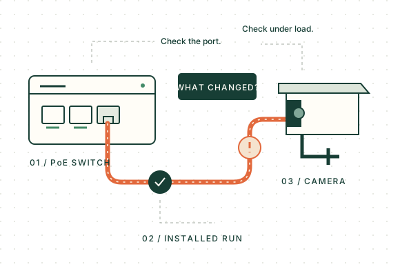
A PoE voltage reading does not prove that enough power reaches a camera while it is working. Check the camera’s required PoE type, the port limit and the switch’s shared budget. Compare a short known-good copper lead with the installed run, and record what changes when infrared lighting, a heater or PTZ movement starts.
03One cable. A crowded cabinet.
Choose the method from the cable’s connection state. A compatible port-blink function or switch discovery can identify an active port. Use a tone-and-probe system explicitly rated for the connected network when tracing conductors. A cable being safe to test disconnected does not mean the same socket or mode is safe on a live PoE port.
NEXT-STEP FINDER
What’s happening on site?
Choose the guide that matches the observed symptom, then check the relevant connection state before using a tester. A slow link, a restarting camera and an unidentified cable call for different first checks. The finder points to those checks; it cannot determine a fault from the symptom alone.
Confirm both ports support gigabit, then compare with a known-good short lead.
Follow the troubleshooting steps →FROM THE FIELD GUIDE
What does your tester actually prove?
Verification checks basic wiring, qualification assesses support for a stated network application, and certification measures a link against a selected cabling standard. A cable tracer or PoE detector answers a different question. Choose the capability required by the job, then check the exact instrument’s manual and limitations before interpreting a PASS.
Verification, qualification or certification?
Verification checks basic wiring. Qualification assesses support for a stated network application. Certification measures an installed link against a selected cabling standard and test limit. Choose the level from the job’s acceptance requirement: a continuity pass does not certify Cat6 or Cat6A, and the tester’s brand does not define the test level.
Read the guideHow to trace an Ethernet cable at a switch
Choose the method from the cable’s connection state. A compatible port-blink function or switch discovery can identify an active port. Use a tone-and-probe system explicitly rated for the connected network when tracing conductors. A cable being safe to test disconnected does not mean the same socket or mode is safe on a live PoE port.
Read the guideNOYAFA NF-8209S: check the capability, not just the name
Verify the exact NF-8209S unit, manual and firmware before relying on a feature. Cable mapping, length measurement, port flashing, tracing and PoE identification answer different questions. None of those feature names alone proves cabling certification or PoE load-testing capability. WireTrace UK has not yet bench-tested this model; this page is a checking guide, not a hands-on review.
Read the guideTHE FAULT REFERENCE
Why can correct pin continuity hide a split pair?
A split pair can connect matching pins at both ends while using conductors that are not physically twisted together as required. A simple continuity sequence can therefore pass without proving correct pairing. Compare opens, reversed pairs, crossed pairs and split pairs in the illustrated reference, then record the actual instrument result.
Explore the fault library ↗What evidence supports these guides?
These guides explain manufacturer documentation and attributed technical cases, with the limits of each source kept alongside the claim. Fluke’s testing guidance distinguishes verification, qualification and certification; the FOA illustrates wiremap faults. Our fault drawings explain the principles, while original measurements will be labelled only after the tests have actually been performed.